How Electronics simulator Works?
This simulator is done in Javascript because it has to work in the browser. In simulation it parses the diagram and creates a system of equations describing the voltage and current at each point in the diagram. The voltage equations are basically "Ohm's Law" and the current equations are "Kirchoff's Law". Once we have the equations, We need to solve the equations to know the values. it is implemented by linear equation solver. Finally we have a unique values of each nodes and update these values to draw this circuit.
For example : The Resistor
The resistor is the 2-terminal device. Its symbol and characteristic are
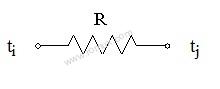
Vi - Vj = R Ii
where Ii is the current entering terminal ti and Vi and Vj are the voltages at terminals ti and tj.
R is the"resistance" of the resistor. Physically resistors are bought as such. The degree to which this mathematical idealization describes a real resistor is particularly excellent.
There is another number concerning the resistor above that is of interest. It is called the power dissipated. This number does not appear in network analysis but it is of importance for considerations outside of network analysis.
The power dissipated is:
RIi2 = (Vi - Vj) , Ii =(Vi - Vj)2/R
Physical resistors have a maximum power they can dissipate without being damaged or destroyed. They generate heat and the power dissipated is exactly the heat power generated.
Voltage Source
The next 2-terminal device is the voltage source with the symbol and characteristics:
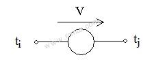
Vj - Vi = V
where Vi and Vj are voltages at terminals ti and tj. V is the value of the voltage source.
There are many devices that are well described by voltage sources: flashlight batteries, car batteries, the 115V wall receptacle and power supplies operated in their usual mode. Also, there are voltage regulator diodes called Zener diodes that are described well by voltage sources over a limited range of conditions.
Let us analyze one resistor circuit:
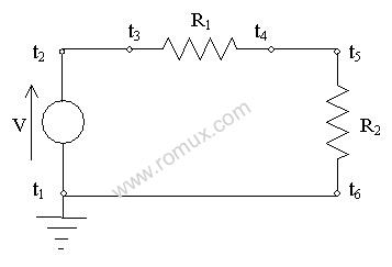
There are 3 devices containing 6 terminals. There are 3 links: l2,3, l4,5, l6,1,and obviously 3 nodes we will call N1, N2, N4 (naming them after the lowestnumbered terminal in the node). Consequently, there are 3 currents, I2,3,I4,5, I6,1, and 3 voltages, V1, V2,V4.The topology requiresthat the total current entering each device is zero:
I6,1 - I2,3= 0
I2,3 - I4,5= 0
I4,5 - I6,1= 0
The device characteristics are:
V2 - V1= V
V2 - V4= I2,3 R1
V4 - V1= I4,5 R2
In addition, we dictate that the node containing terminal 1 is ground so we have
V1 = 0
Looking at the first 3 equations we immediately see that if there is any solution at all, all 3 currents must be equal. (As a point of interest, you will also note that of these first 3 equations, which come from the topology, 1 equation, any one of them, is redundant. We could leave any one of these 3 equations out and lose nothing.) From the rest of it we quickly get
V1 = 0
V2 = V
V4 = V (R2/ (R1 + R2))
I2,3 = I4,5= I6,1 = V / (R1 + R2)
This is the unique solution.
User Comments
No Posts found !Login to Post a Comment.