Reset
Reset is used for putting the microcontroller into a 'known' condition. That practically means that microcontroller can behave rather inaccurately under certain undesirable conditions. In order to continue its proper functioning it has to be reset, meaning all registers would be placed in a starting position. Reset is not only used when microcontroller doesn't behave the way we want it to, but can also be used when trying out a device as an interrupt in program execution, or to get a microcontroller ready when loading a program.
In order to prevent from bringing a logical zero to MCLR pin accidentally (line above it means that reset is activated by a logical zero), MCLR has to be connected via resistor to the positive supply pole. Resistor should be between 5 and 10K. This kind of resistor whose function is to keep a certain line on a logical one as a preventive, is called a pull up.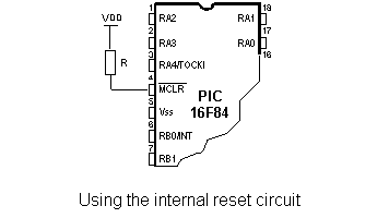
Microcontroller PIC16F84 knows several sources of resets:
a) Reset during power on, POR (Power-On Reset)
b) Reset during regular work by bringing logical zero to MCLR microcontroller's pin.
c) Reset during SLEEP regime
d) Reset at watchdog timer (WDT) overflow
e) Reset during at WDT overflow during SLEEP work regime.
The most important reset sources are a) and b). The first one occurs each time a power supply is brought to the microcontroller and serves to bring all registers to a starting position initial state. The second one is a product of purposeful bringing in of a logical zero to MCLR pin during normal operation of the microcontroller. This second one is often used in program development.
During a reset, RAM memory locations are not being reset. They are unknown during a power up and are not changed at any reset. Unlike these, SFR registers are reset to a starting position initial state. One of the most important effects of a reset is setting a program counter (PC) to zero (0000h) , which enables the program to start executing from the first written instruction.
Reset at supply voltage drop below the permissible (Brown-out Reset)
Impulse for resetting during voltage voltage-up is generated by microcontroller itself when it detects an increase in supply Vdd (in a range from 1.2V to 1.8V). That impulse lasts 72ms which is enough time for an oscillator to get stabilized. These 72ms are provided by an internal PWRT timer which has its own RC oscillator. Microcontroller is in a reset mode as long as PWRT is active. However, as device is working, problem arises when supply doesn't drop to zero but falls below the limit that guarantees microcontroller's proper functioning. This is a likely case in practice, especially in industrial environment where disturbances and instability of supply are an everyday occurrence. To solve this problem we need to make sure that microcontroller is in a reset state each time supply falls below the approved limit.

If, according to electrical specification, internal reset circuit of a microcontroller can not satisfy the needs, special electronic components can be used which are capable of generating the desired reset signal. Beside this function, they can also function in watching over supply voltage. If voltage drops below specified level, a logical zero would appear on MCLR pin which holds the microcontroller in reset state until voltage is not within limits that guarantee accurate performance.
User Comments
No Posts found !Login to Post a Comment.